"Annotation Extracts and UDF's for Manufacturing"
Here is a bit of instructions for setting up and using UDF’s for both Design and Manufacturing.
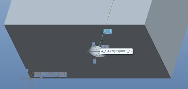
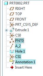
We’ll start by looking at a specific hole feature on a part.
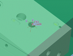
This is a ‘standard’ hole, created with a sketched feature.
Next, I created a ‘blank’ part, to use as the basis for the UDF / Annotation feature.
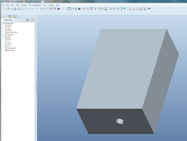
I started with a basic protrusion, no need to get fancy.
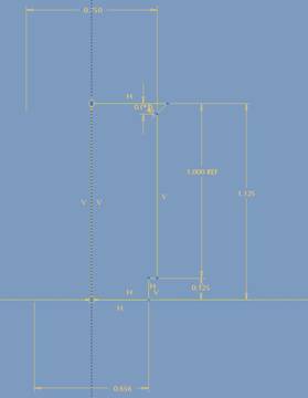
Next, I created a coordinate system on the start surface for drilling the hole. I then created a point, referencing the csys, followed by an axis. The point is used for creating the axis, and the axis will be used when we create the hole. You could probably just use the Z axis of the csys to create the axis now in WF5, but we do need some supporting geometry to get things rolling.
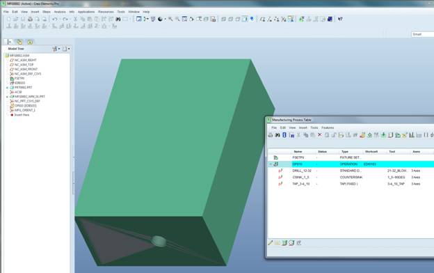
After the point / axis / hole is created, create a manufacturing model with this part as the reference model. 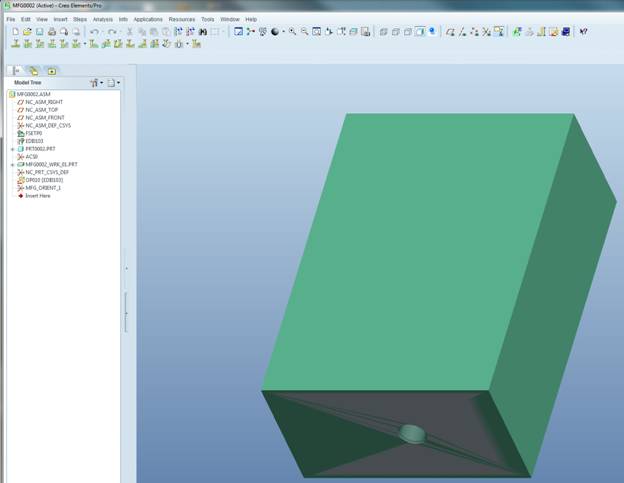
Create the desired sequences. In this case, I added drilling, countersinking, and tapping sequences.
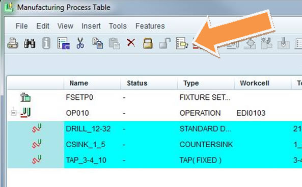
Highlight all three sequences, then select the Create Template icon in the process manager…
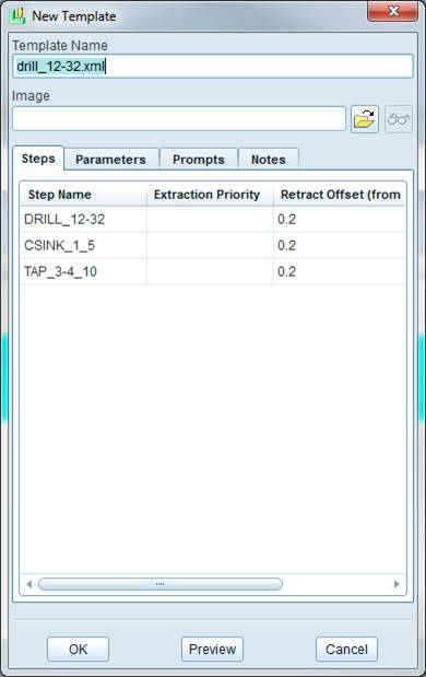
Enter the desired name for the XML template.
Here’s where the fun starts.
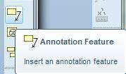
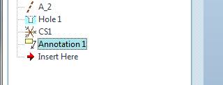
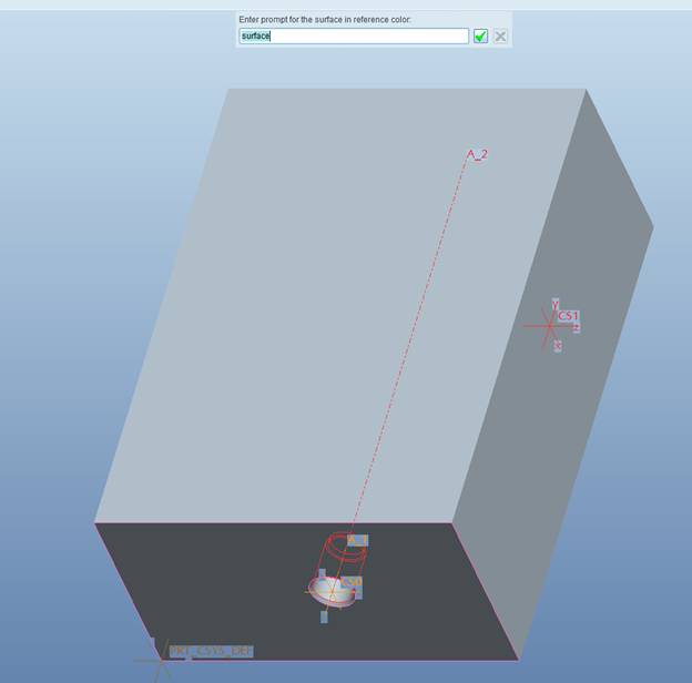
We’ll go back to the reference part model, and create an annotation feature.
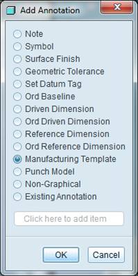
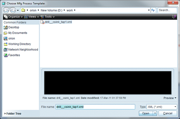
We want the Manufacturing template option. Pick, and then select OK. Next, we’ll navigate to the location new stored the xml template. Select it, and then select Open.
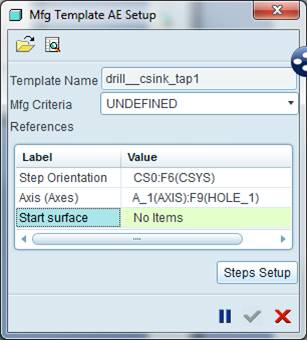
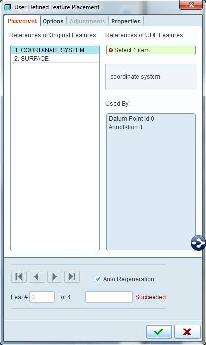
We need to select the references to include in the annotation feature.
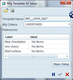
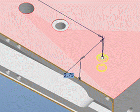
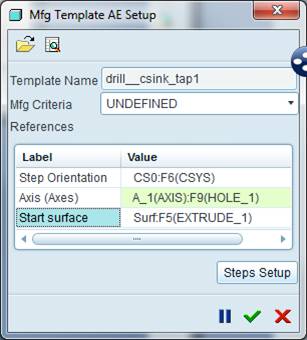
Notice what we’re looking for: a step orientation (think csys), and axis (for the hole) and a start surface. Let’s go select them.
Csys selected, now previewing the axis…
Finally, the start surface.
Hit the green check mark…
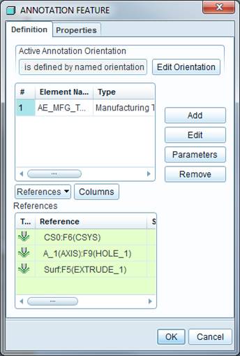
Followed by OK. We just created the annotation feature.
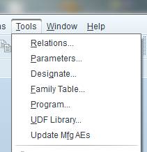
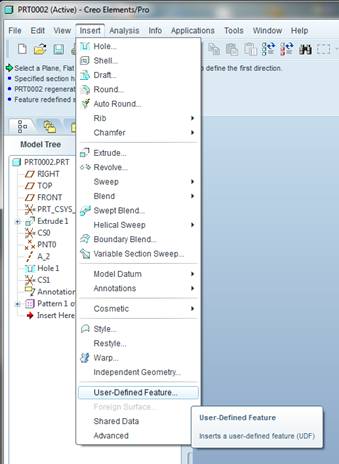
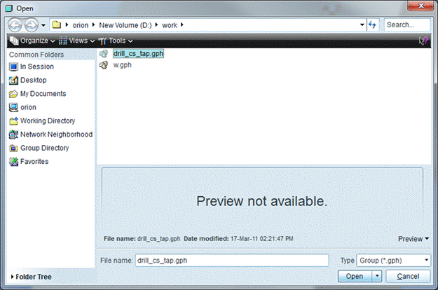
The last step is creating the UDF. Select tools > UDF Library…
Create, and enter the name.

I entered drill_cs_tap as the name.
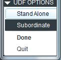
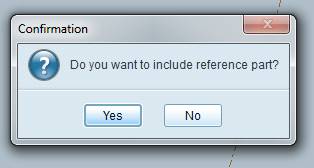
We’re prompted to enter the information for the references to place the UDF. We’re going to make this as a stand alone UDF that copies the reference model into it.
Select the features you want in the UDF…
Next, select Done > done/Return Single Done Return
The system will then ask you to enter the question for placing the UDF.
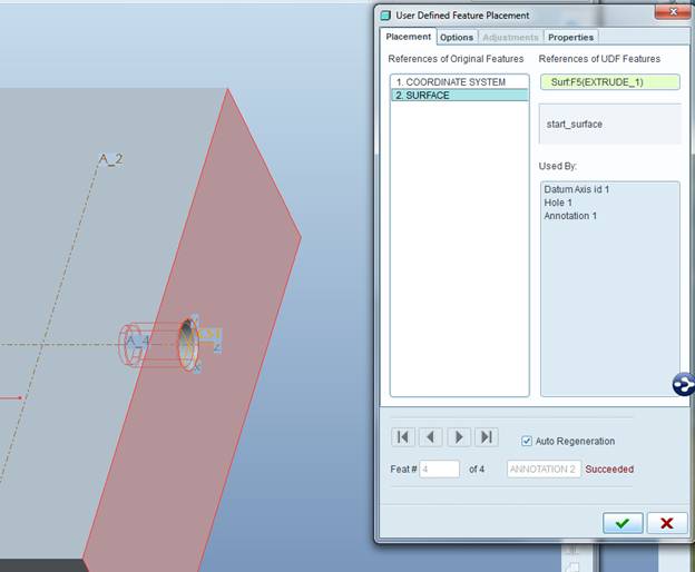
Finally, we provide the prompt for the start surface.
It’s a little tough to see, but the start surface is actually highlighted in purple.
Should be able to select OK, and Done to finalize the UDF creation.
Using the annotation feature is easy. Let’s look at that process next.
The UDF is placed via a csys. I added a few new coordinate systems to the previously used reference model.
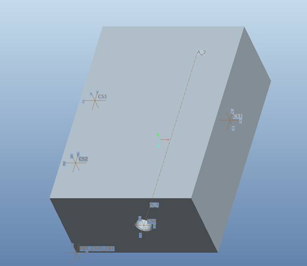
Note that all we have to define is the csys, and the start surface.
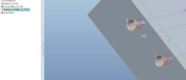
And of course you can utilize patterns…
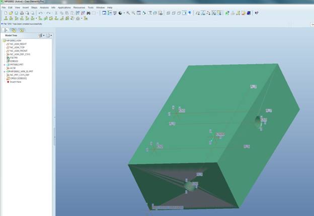
Next, we look at the mfg model.
From the process manager, we’ll create an extract feature… ![]()
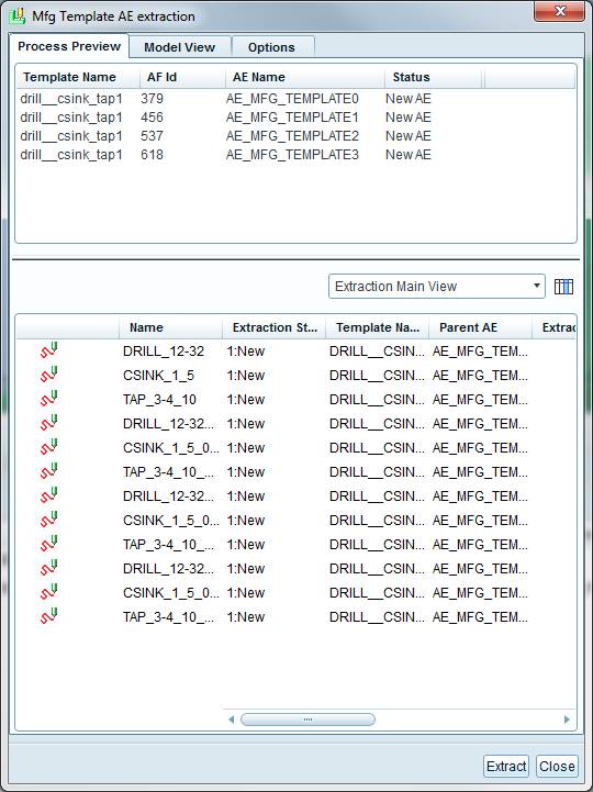
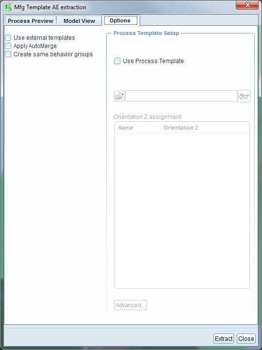
Note that the options tab will allow you to automerge sequences that use the same csys.
Select the extract…
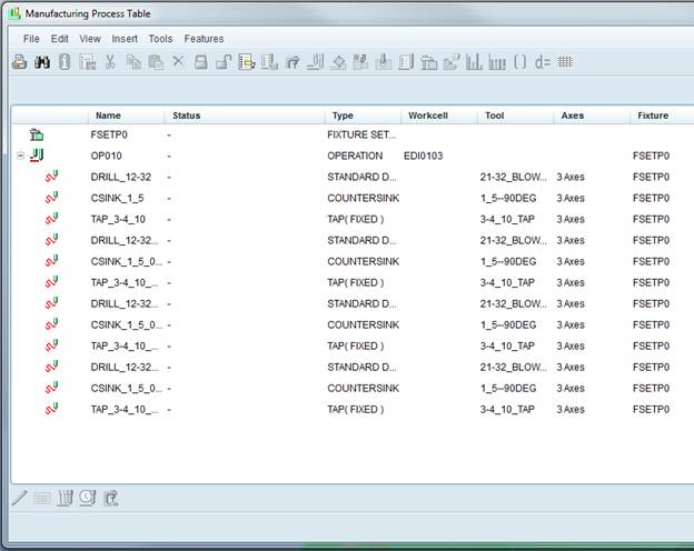
From there, you can simply drag and drop the sequences to reorder them as needed.
Keep in mind that I’ve shown how to apply this technique to simple holes. We should consider using this for more than just holes.